Gas Generator (GG)
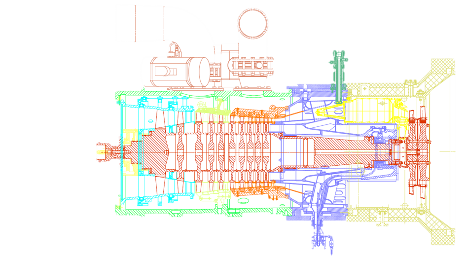
The gas generator generates a flow of pressurized hot gas, driving the power turbine.It is consist of 4 main parts: Inlet, Compressor, Cumbustion chamber and Compressor rotor.

siemens-energy determined Head Groups (HG) for each part of turbine, in order to be recogniosable by any body who want to work with SGT-600. It also help for supplying segments in installing and overhaul period

This HG is a very important part of the turbine. Because basement of bearing No1 is inside of this HG. And also air will goes inside the machine from this HG.
many sensors are located in this part. Rotor of Gas generator will adapts its own axial displacement from this part. passage of Lubrication of bearing No1 are located inside of this HG. this part has a role for making many measurements during assembly of gas generator.
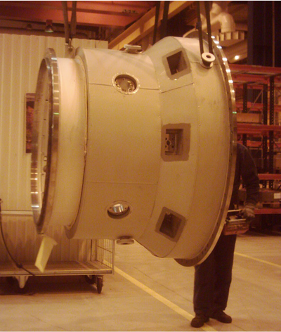
And also has a important role for sealing of bearing No1. if you have a deeper look in to this part, you will notify that from the manufacturing view, this part has many casting parts, forges part. After welding HG 4210 has a huge machining and very restricted tolerances. So it means even during handling and lifting of this Hg you should care about the way of this handlings.
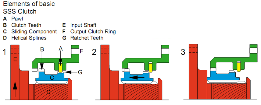
Basic Principles of Operation:
The initials “SSS” denote the 'Synchro-Self-Shifting‘ action of the clutch, whereby the clutch teeth are phased and then automatically shifted axially into engagement when rotating at precisely the same speed. The clutch disengages as soon as the input speed slows down
relative to the output speed.
The basic operating principle of the SSS Clutch can be compared to the action of a nut screwed on to a bolt. If the bolt rotates with the nut free, the nut will rotate with the bolt. If the nut is prevented from rotating while the bolt continues to turn, the nut will move in a straight line along the bolt.
In an SSS Clutch the input shaft (E) has helical splines (D) which correspond to the thread of the bolt. Mounted on the helical splines is a sliding component (C) which simulates the nut. In the diagram, the sliding component has external clutch teeth (B) at one end, and external
ratchet teeth (G) at the other.
When the input shaft rotates, the sliding component rotates with it until a ratchet tooth contacts the tip of a pawl (A) on the output clutch ring (F) to prevent rotation of the sliding component relative to the output clutch ring.
As the input shaft continues to rotate, the sliding component will move axially along the helical splines of the input shaft. When a ratchet tooth is in contact with a pawl tip, the clutch engaging teeth are perfectly aligned for
inter-engagement and thus will pass smoothly into mesh
in a straight line path. As the sliding component moves along the input shaft,
the pawl passes out of contact with the ratchet tooth, allowing the clutch teeth to come into flank contact and continue the engaging travel. Note that the only load on the pawl is that required to shift the lightweight sliding component along the helical splines.
Driving torque from the input shaft will only be transmit-ted when the sliding component completes its travel by contacting an end stop on the input shaft, with the clutch teeth fully engaged and the pawls unloaded ,When a nut is screwed against the head of a bolt, no external thrust is produced. Similarly when the sliding component of an SSS Clutch reaches its end stop and
the clutch is transmitting driving torque, no external thrust loads are produced by the helical splines. Where necessary, an oil dashpot is incorporated in the
end stop to cushion the clutch engagement. If the speed of the input shaft is reduced relative to the output shaft, the torque on the helical splines will re-
verse. This causes the sliding component to return to the disengaged position and the clutch will overrun.
At high overrunning speeds, pawl ratcheting is prevented by a combination of centrifugal and hydrodynamic effects acting on the pawls.
The basic SSS Clutch can operate continuously engaged or overrunning at maximum speed without wear occurring.
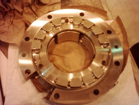
Compressor Bearing(Bearing 1), and it is including 2 bearings, trust bearing and journal bearing.
so this bearing has two main part , trust bearing and journal bearing.,
Type of this bearing Is anti friction type and has brass pads.
If you have more detailed study on this baring, you will found that trust pads of this bearing are two type, main trust pads and reverse trust pads.
Main trust pads will damp axial force when rotor goes to front and reverse trust pads will damp axial force when rotor returns.
Also thermocouple for measuring temperature of oil in bearing no 1 are assembled in this bearing. Mentioned sensors are sensing temperature. In journal bearing you have temperature of bearings pads but in axial bearing you have oil temperature.
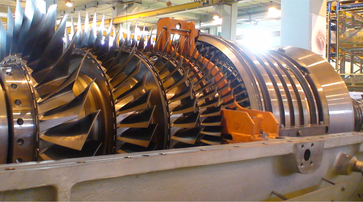
A 10 stage axial-flow compressor is used to compressed the air.
The compressor consists of three major parts. Two low-pressure sections with two and three stages, respectively, and one high-pressure section with 5 stages.
To control the air flow to the compressor, the engine equipped with 2 variable guide vane stages(stages 0 and 1). These are of the variable geometry type,actuated via a spindle control mechanism and a variable speed electric motor.
The rotor assemblies are built up of several electron-beam welded disks and an intermediate shaft is welded on to the rotor.
A diffused section after the compressor functions to decelerate the compressor discharge air flow to maintain pressure and to direct the air into the combustion chamber.
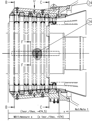
This HG(head group) is the biggest stationery casing in the Gas generator and this casing is effecting many measurements during assembly. Mentioned HG has a role for acting as a cover for all inside parts and casings.
HG 4250 is the place that bleed valves are assembling. And also base of IGV is assembled in this HG.
this part is a casting part that should be machined properly. If you look to the Gas generator you will notify that many internal casings are assembled inside of this HG.
During transportation of Gas turbine you need some place to connect special tool for lifting of unit. HG 4250 is the place that you can connect one part of lifting tool.
one side of this HG is HG 4210 and another side is HG4310. it means that this HG is very important in working of Gas Turbine.
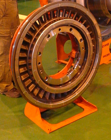
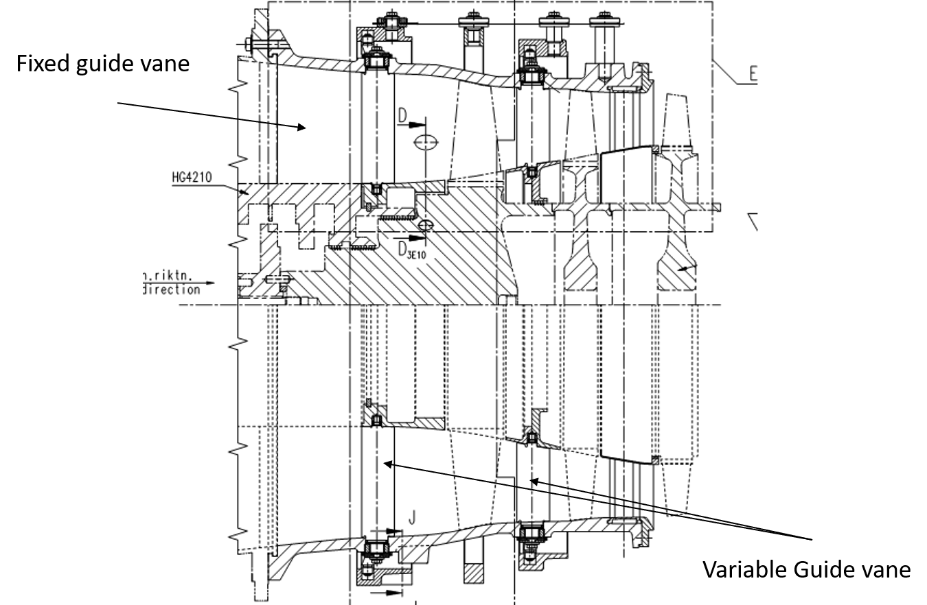
Gas Generator is a axial compressor, it means that you should have some rotary blades and also stationary vanes. This HG is the basement for first 3 stages of the compressor.
This HG has two types of vanes, fixed vanes that known as CGV, and variable vanes that known as VGV. this VGV vanes works with actuator, this combination make IGV system. That its is very important during change of speed of the rotor or avoiding of purge in the compressor.
Also remember that after some ours of running of engine you have to check tip clearance of blades with this casing with using filler gauge.
Centre of this casing its exactly in the center of rotor.
After HG 4251, this HG is located, and stages 3,4,5 of the fixed vanes are assembled . Tip clearance of blades and casing is little tighter that HG4251.
Another important matter for this HG is connecting type with the HG 4250. this part its not direct bolted to HG4250, by using 3 ex center shafts , this HG connect to the HG4250. this ex center shafts can align casing with rotor. So after some hours of working of Gas Turbine you should measure tip clearance and align this casing with the rotor.
All of the vanes are fixed to the casing in this HG. And there is not any IGV system in this casing.
Between this HG and HG4251, there is a cavity that air goes out and when bleed valves are open , goes out from the casing. This part is working in the cold section of the turbine.
Also in the end of this HG there another cavity that most part of leaking air will use for cooling guide vanes in stage 3 of Power turbine. And center of this HG is in the center of rotor.
Last part of the compressor internal casings is HG4253. and after it, we have hot section parts. Stages 6,7,8 ,9,10 are located in this HG. And connection with the Hg 4250 is ex center shafts.
Tip clearance between rotor blades and casing here is minimum value and if you have vibration in the rotor out of controlled value , you can see sign of this value as scratching of casing here. .
Length of the blades here is minimum value and blades in this place are very brittle. .
This HG from end side is connected with HG4310.
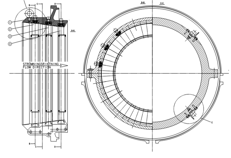
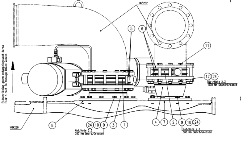
In compressor some times you need to manage volume of the air . So you need to have valves that let the air goes out from compressor system.
For this manner in SGT 600 we have two bleed valves, one of the working as open or close valve, but another is a controllable valve.
Place of mentioned valves are in top of HG 4250. in SGT 600 gas turbine , this valves pass the air from compressor to inlet air.
This HG containing solenoid valves , air ducts , and small pipes. We call air ducts HG5262
This HG(Head group) is one of the critical casings in the Gas generator. From one side this HG is start of hot part of turbine. Combustion chamber is located in one side of this HG. Also bearing No 2 that is very sensitive also will assemble in this HG.
Even rotor will assemble from inside of this HG and all of sealing component for bearing No2 is located in This HG.
We have thermo couples for bearing No 2 and also vibration transducers in this HG. And also guide vane No1 after combustion chamber will assemble in this HG.
From manufacturing view this casing is including casting parts, forging parts and many heavy welding. This HG containing two main part inner casing and outer casing that connecting to each other just by four ex center shafts. And they can adjust.
Inside of this HG there is one sealing gland that if you have sever vibrations this sealing will broken and should be changed.
This HG is bearing No2 of gas turbine. As you know bearing No 2 in Siemens SGT600 gas turbine is a very critical part. Nominal pressure of oil is about 14 bar and speed of rotor is 9000 RPM.
this bearing has special lubricating system, including boosting pumps and special oil tank. namely pressure of this Bearing is 14 bars. And huge volume of oil will pass this bearing. It means that lubricating line of this bearing is very special. Type of this bearing is anti frictional bearings that including pads, and it is journal bearing.
outlet of this bearing is located in HG4310 and from this HG oil goes to special tank.
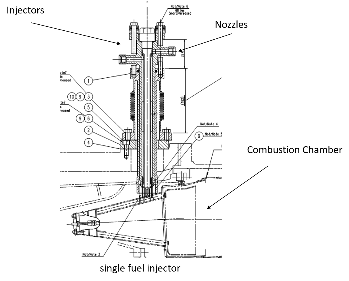
For running the gas Turbine we need to have fuel. This fuel should have needed pressure and also needed mass flow. This special mass flow is controlled by nozzles.
This nozzles are inside of this HG. Inside of HG 5051 there is two passage for main fuel and pilot fuels.
SGT 600 Siemens gas turbine can run with liquid fuel also, at that time you have to use dual fuel injectors. In this type of injectors you will have two more passages, one for liquid fuel and one for water.
In some early SGT600 for having low nox and also for having cold flame during usage of gas turbine they use water and also one manifold for water.
Nowadays after improvement of materials in the combustion chamber water its not used.
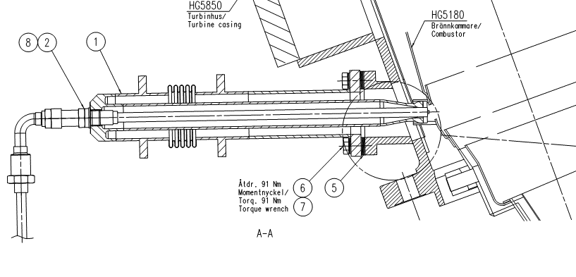
After having mixture of fuel and air , we have to have ignition system for having good flame.
This ignition system in including one structure and spark plug.
Now type of this ignition system is changed , in older Siemens Gas Turbines that mentioned structure was including one vessel for flame up. And two spark plugs that producing flame. And also in old version one flame detector was in top of ignition component.
But in newer versions flame is forming inside of the combustion chamber and spark plugs are directly inside of combustion chamber
In the next page you can see both two type of ignition system.
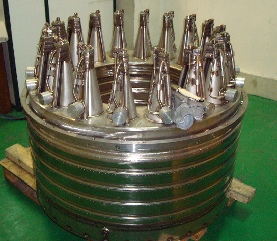
The combustion chamber in gas turbines and jet engines (including ramjets and scramjets) is called the combustor.
The combustor is fed high pressure air by the compression system, adds fuel and burns the mix and feeds the hot, high pressure exhaust into the turbine components of the engine or out the exhaust nozzle.
In SGT600 gas turbine combustion chamber has 18 burner that are welded to the body, two place two place for flame detectors. And one place for ignition system.
Burners in SGT 600 has two passage for gas ( main and pilot) and two cone that make rotary movement of are.
Inside of combustion chamber is coated by special coating resistant ( thermal barrier coating)to high temperature.
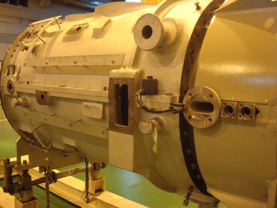
Name of this HG is Turbine Casing and covers turbine of gas generator and also combustion chamber. And also in the end of this HG there is a big flange that this flange is place of assembly of Power turbine.
All of the flame detectors and also ignition system are assemble in this casing. Body of this casing is including forged parts and huge welding.
This HG works in hot section of Gas generator and has many insulations that avoid leaking of heat to out side. This insulations are including some metal sheet insulations, and soft textile insulations.
Even in the place of connecting Power turbine to the gas generator there is some metal sheet insulations.
Connection of the guide vane No 2 with this HG is ex center shafts, and you can adjust this guide vane with this ex center shafts.
This HG is including two parts:
Guide vane stage 1
Guide vane stage 2
After combustion chamber there is one stage of the vain that also is called nozzles, after it there is one stage of the gas generator disk, and after it there is guide vane No2.
Connection of the guide vane no 2 to the turbine casing is 4 ex center shafts.